The lathe machine is one of the oldest machine tools in history. An Englishman named Henry Maudslay is credited for designing the lathe machine in 1797. His screw-cutting lathe machine design would be the predecessor of today’s high-speed and heavy-duty lathe machine.
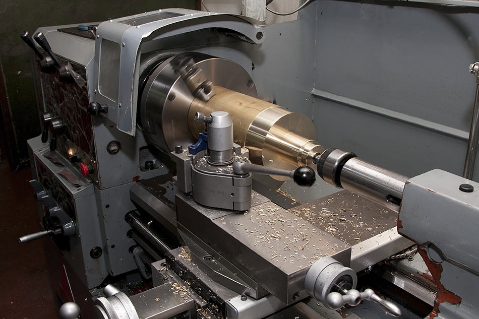
As you may know, the lathe machine is a machine tool primarily used for shaping metal or wood. It rotates the workpiece around an unmoving cutting lathe tool. It removes undesired parts of the material and leaves behind a newly shaped workpiece.
The lathe machine is simply an impressive piece of equipment thanks to its different parts that work well together. Continue reading below to learn more about the parts and functions of a lathe machine.
Table of Contents
Parts of a Lathe Machine
Here is a diagram with all the important parts of a lathe machine.
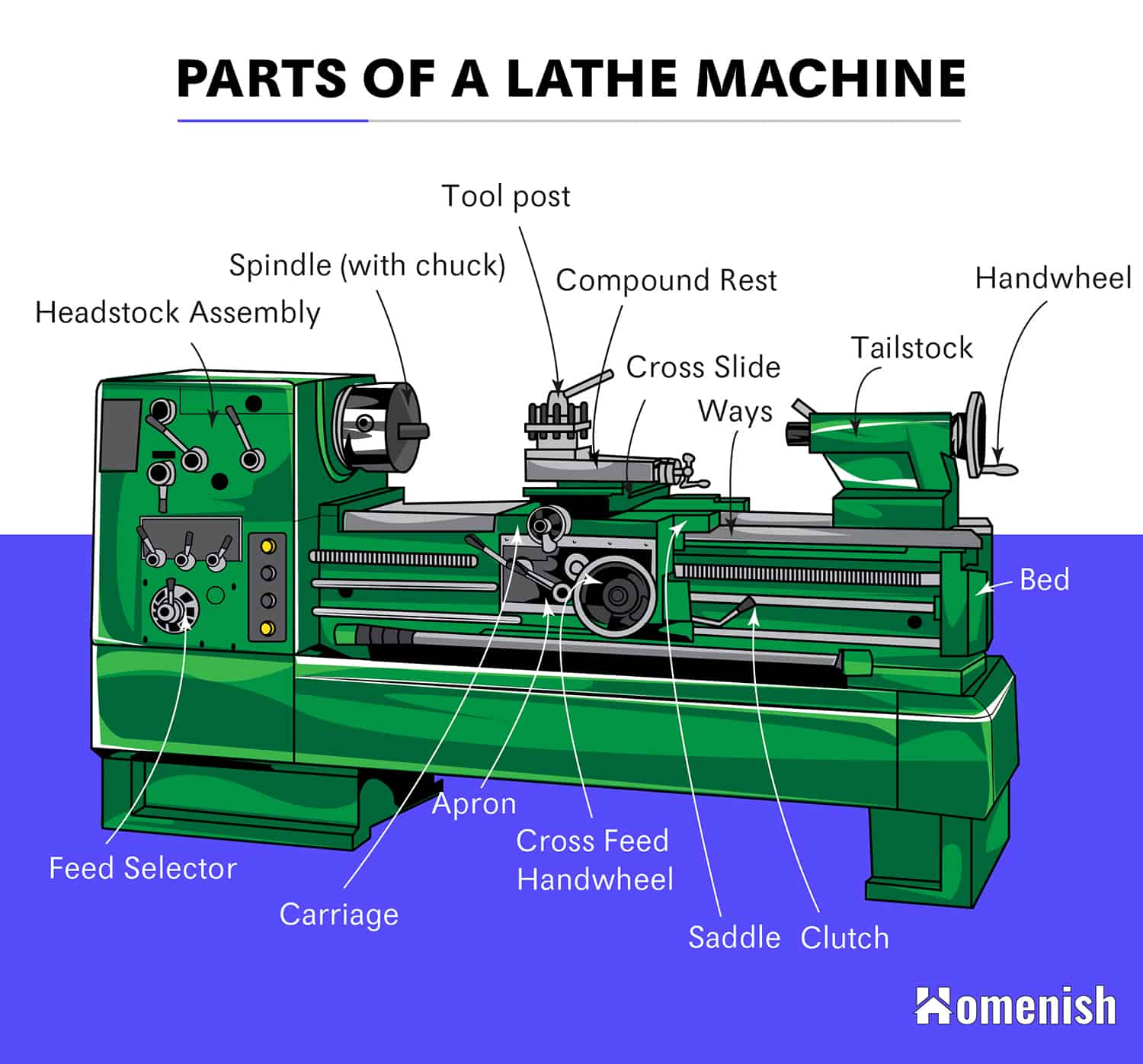
There are six major parts of a lathe machine. These are the bed, the head stock assembly, the main spindle, the tail stock, the carriage, and overload safety devices.
Let’s take a closer look at each main part.
The foundation of the lathe machine, where its various operational parts are bolted or mounted, is called the bed. In effect, the bed forms the base of the lathe machine.
The lathe machine bed is generally made of hardened steel or cast iron. It is heavy and sturdy enough to damp all the vibrations that occur while machining. Large lathe machines may have beds consisting of more than a single piece. Also, the type of lathe machine may dictate or influence the size of the bed.
Broad box-section columns support the bed while its upper surface may be scraped or grounded. It also consists of a couple of heavy metal slides that run lengthwise. Those slides are rigidly supported by cross girths.
There are three major components housed in the bed of the lathe machine– the head stock assembly, the carriage, and the tailstock.
The Head Stock Assembly
The head stock assembly is usually found or installed on the left side of the lathe machine. Its main function is to provide rotational power for the lathe machine. It houses the main spindle in the bearings and ensures that it is aligned properly. It is also where the spindles and gears are located. The gearbox with separate speed changes is also placed below the head stock assembly.
There are also accessories mounted or placed on the head stock spindle. These are the three and four jaw chuck, collet chuck, magnetic chuck, lathe center, lathe dog, and face plate.
The head stock assembly also features a clutch and brake mechanism, which has the pulley coupled to the shafting in the head stock. The spindle brakes automatically when the pulley is running free.
Main Spindle
The main spindle is a hollow cylindrical shaft where long slender jobs can pass through. The main spindle and its bearings are an integral part of the lathe machine as this is deflected by the thrust of the cutting tool.
The spindle nose, or the end of the main spindle facing the tailstock, features a self-locking taper that accommodates the lathe center or collet chuck. It allows rapid mounting and removal of fixtures and chucks. It also facilitates accurate and secure positioning of fixtures.
Tail Stock
The tailstock is a movable casting found opposite the headstock assembly. It serves two purposes. First, it supports the other end of the work or figure when being machined. Second, it holds a tool for performing actions like drilling, tapping, and reaming. The tail stock also has the dead centers, or the hand wheel, and the adjusting screw.
The body of the tailstock can be adjusted on the base, which in turn is bolted on the guideways of the bed. The tailstock’s adjustable body allows for the lining up of the center that is carried in the moving spindle. The dead center in the movable spindle has an axial adjustment in the form of the handwheel. This, in turn, is attached to a screw that engages the nuts at the end of the movable spindle.
Carriage
The carriage is sandwiched between the tailstock and headstock. It is mounted on the bed and slides along its guideways. It can also be locked on the bed by tightening its lock screw or moved manually using the hand wheel.
The carriage consists of five parts: saddle, apron, compound rest, cross slide, and tool post. It looks like the letter H and bridged across the lathe bed to support its three parts, namely the cross slide, tool rest, and compound rest. Critical to the carriage is the apron, which is fastened to the saddle. It contains the gears and clutches for transferring motion from the feed to the carriage.
The carriage is mainly responsible for providing three movements to the tool: longitudinal feed, which is through carriage movement; cross feed, which is through cross slide movement; and angular feed, which is through top slide movement.
Overload Safety Devices
Shear pins and slip clutches are the main overload safety devices of a lathe machine. These parts prevent damage due to the overloading of important parts of the lathe like the gears, lead screws, and feed screws.
The shear pin, for one, is intended to be of a certain diameter and shape. It is designed to withstand a certain torque. When the torque is exceeded, the shear pin causes the machine’s movement or motion to stop.
On the other hand, a slip clutch releases the feed rod when a designated force is exceeded. This protects the feed rod and its connecting mechanisms. The slip clutch likewise permits the feed rod to automatically re-engage once the force is lessened.
Conclusion
As you may have realized, a lathe machine consists of many different parts that work together. These lathe machine parts enable the old and reliable piece of equipment to perform various operations like boring, cutting, turning, forming, tapping, spinning, and polishing, among others.